What Electrical Components We Chose and Why
- Motors – to push a wall that compresses the BVM
- Arduino – to be the brain of the device
- Motor Drivers – to drive the motors with code to go at a set rate and speed
- Limit Switch – for the compression wall to identify when it reaches “home” in terms of linear distance
- LCD Screen – to display the pressure of the patients’ lungs and warm user when to stop the device
- AC/DC 12V Adapter – to provide primary power to the device
- 12V DC Rechargeable Battery – to provide backup power when needed
- DC 12V Fan – to dissipate heat inside the device due to the use of the motors and motor drivers
- 3-Way Switch – to allow the user to switch between off, wall power, & battery power
- Emergency Stop – to ensure the capability of the user to quickly cease all power to the device in an emergency state
- LED Light – to indicate to the user that the device is powered on
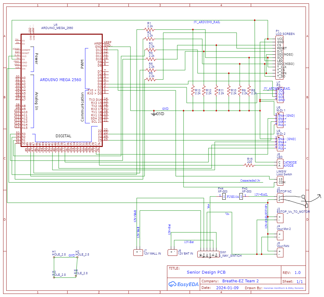
Our Electrical Design for the PCB – including all inputs and outputs
Our PCB Revisions
Revision 1:
Our mounting holes were not grounded and neither were any of the Arduino rails!
Revision 2:
We ordered this one by mistake and meant to order what is “Revision 3” instead.
Revision 3:
Our final revision but it could have used a little more cleanup. The main focus of this revision was putting the output and input terminals near where they will actually be in the housing.
Power Calculations
| Component | Wattage (W) | Voltage (V) | Current (A) (max) | Watt-Hours (Wh) | Amp-Hours (Ah) |
| Motor 1 | 12 | 12 | 1 | 6 | 0.5 |
| Motor 2 | 12 | 12 | 1 | 6 | 0.5 |
| Arduino Uno | 2.4 | 12 | 0.2 | 2.4 | 0.2 |
| Fan | 1.44 | 12 | 0.12 | 1.44 | 0.12 |
| Total | 27.84 | 48 | 2.32 | 15.84 | 1.32 |
How Everything Is Put Together
Pictures along the way of how it all came together quarter by quarter.
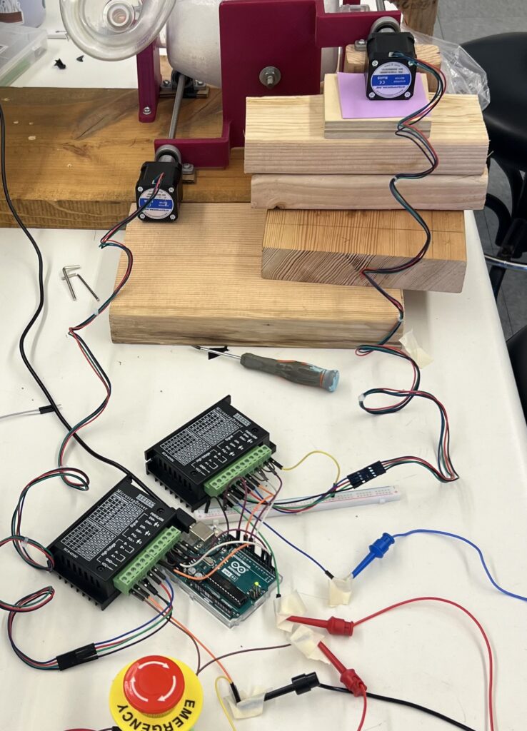
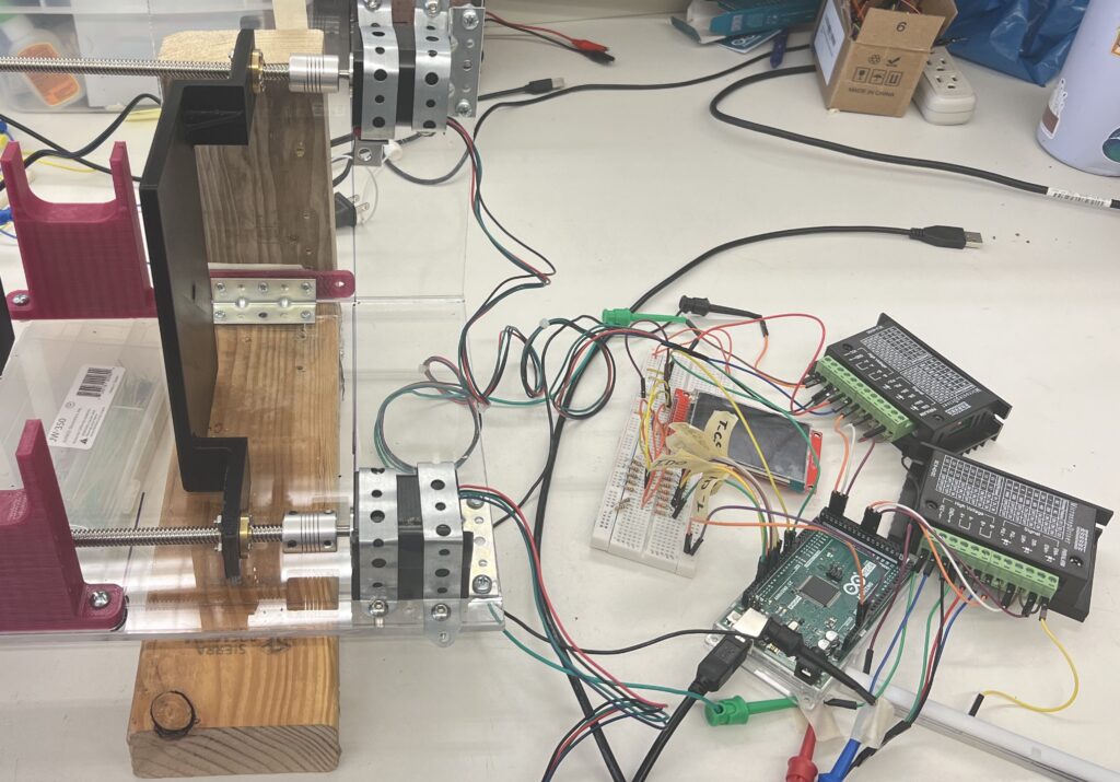
First Motor Setup
Here is the first wiring setup we had to test the motors and motor drivers on the compression panel subsystem. It took a long time to get the code working but once it did we were super excited!
Motor and LCD/Pressure Sensor Subsystems Integration
The next quarter we were able to start the integration of these separate subsystems to merge onto one Arduino in order to draft the final main code.
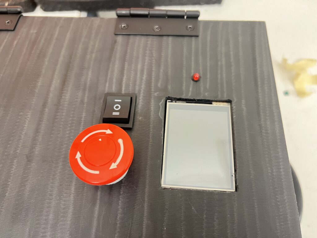
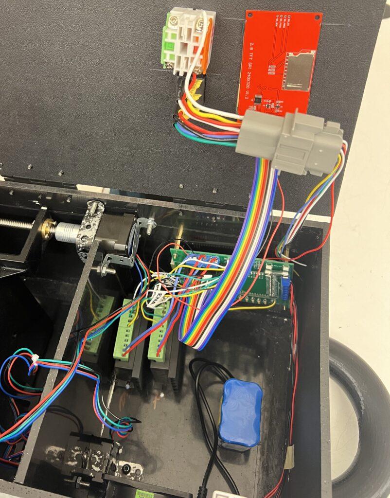
All Electrical Systems Integrated Into the Housing
Once testing of ensuring the PCB worked we were able to wire it into the mechanical engineer’s housing and finalize sizing and cutting.