Mechanical and Electrical Housing

The mechanical housing of a BVM device refers to the physical components that make up the device, including the bag, valve, mask, and casing. The design and quality of these components are critical for several reasons like durability, reliability, and ease of use.
The electrical housing encompasses the electronic components and circuitry that power automatic BVM devices. These components are essential for delivering consistent and controlled ventilation, especially when manual operation is not feasible. Key aspects of the electrical housing include: consistency, control, and safety features.
Compression Subsystem
This subsystem’s goal is to adequately compress the BVM (Bag Valve Mask) in a controlled manner to deliver air to the patient.
How the Subsystem Works
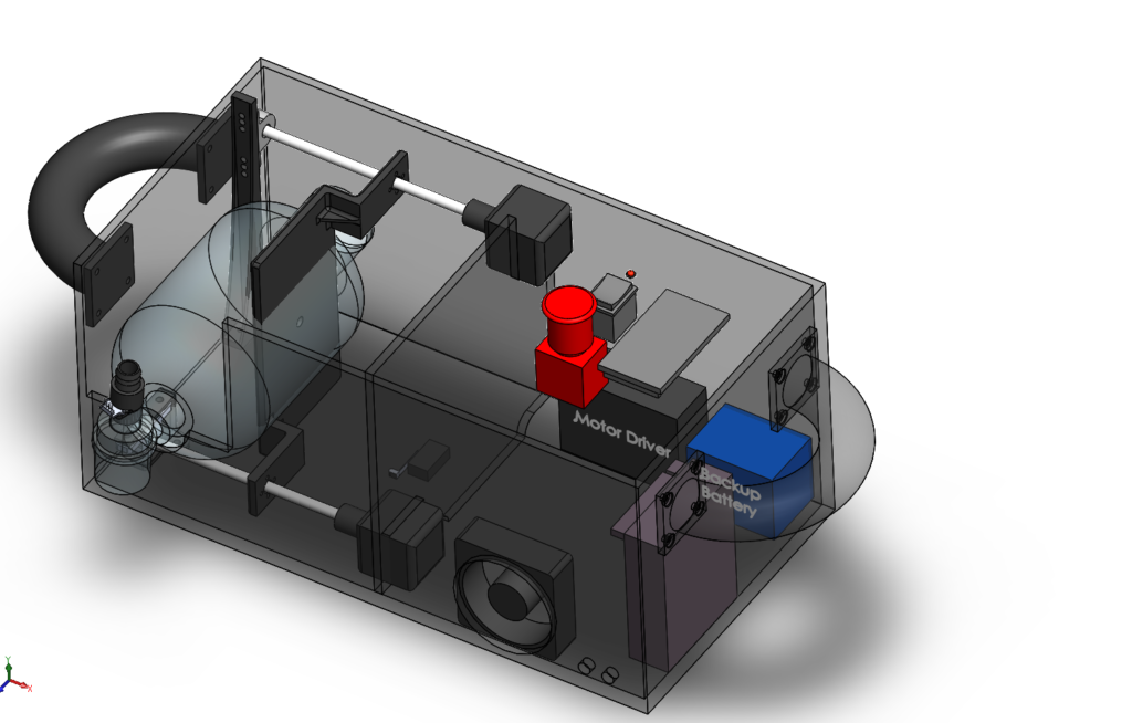
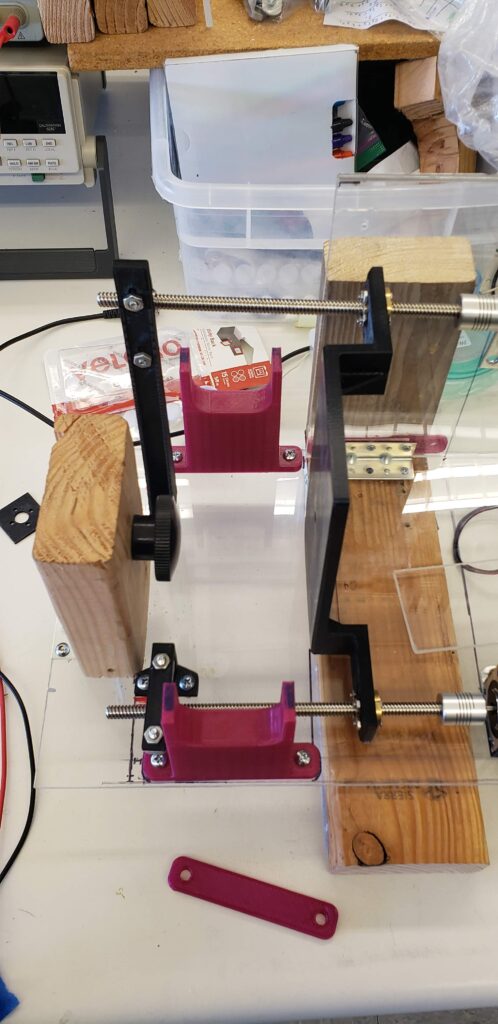
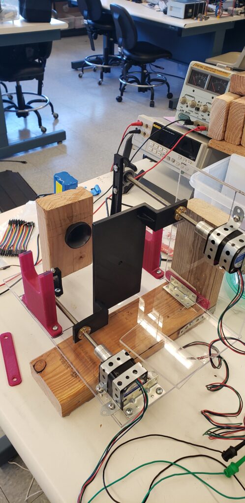
The design consists of two stepper motors that move lead rods back and forth, allowing the motor’s rotational motion to be translated into linear motion. This allowed us to attach a wall, better known as the compression wall, to deflate the BVM held still at the end of the track.
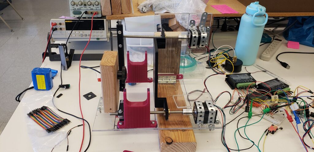
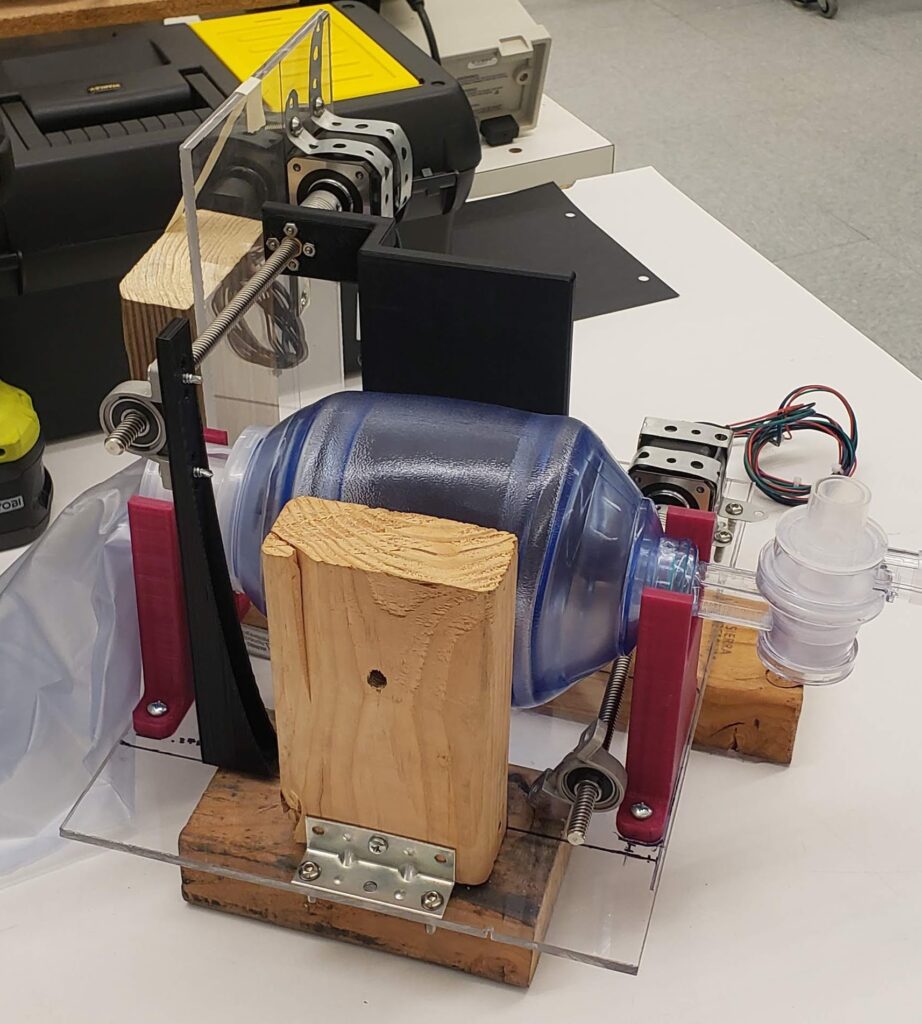
These design choices were made mostly due to the immense accuracy of the stepper motors. Their “steps” allow us to understand the linear displacement we’d need to deflate the BVM to the correlated tidal volume of air pushed out to the patient.
Through testing, we learned that there is a near-linear relationship between the volume of air outputted and the linear distance that the compression wall was displaced.
Pressure Sensor Adapter
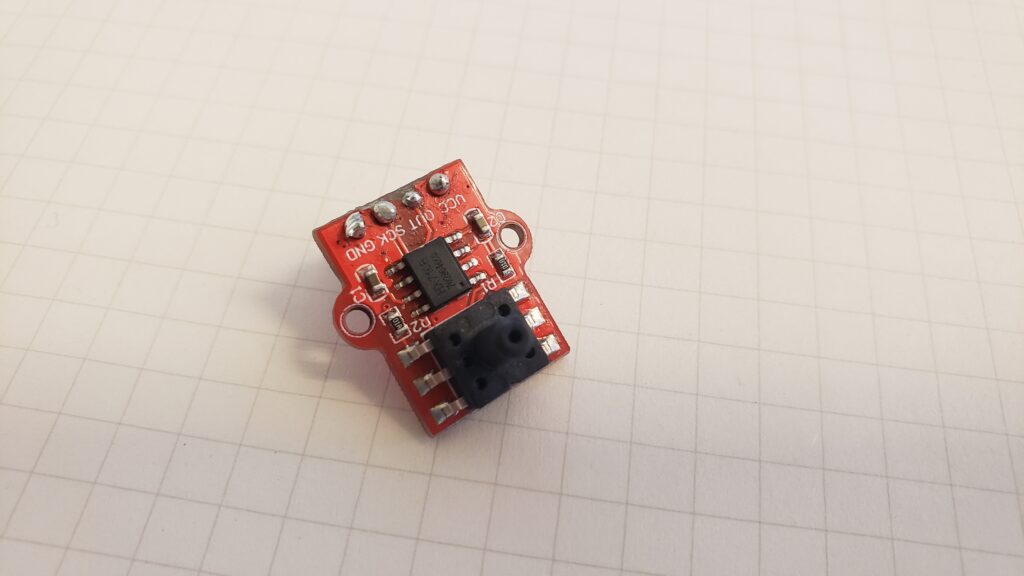
The pressure sensor needed a place to live… in other words, it needed a housing to be able to sense pressure differences within the patient’s lungs.
The adapter was designed to sit in the crossflow of air flowing from the BVM to the lungs.
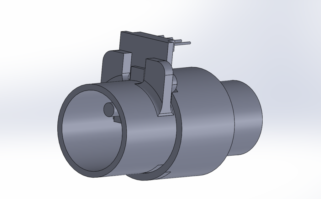
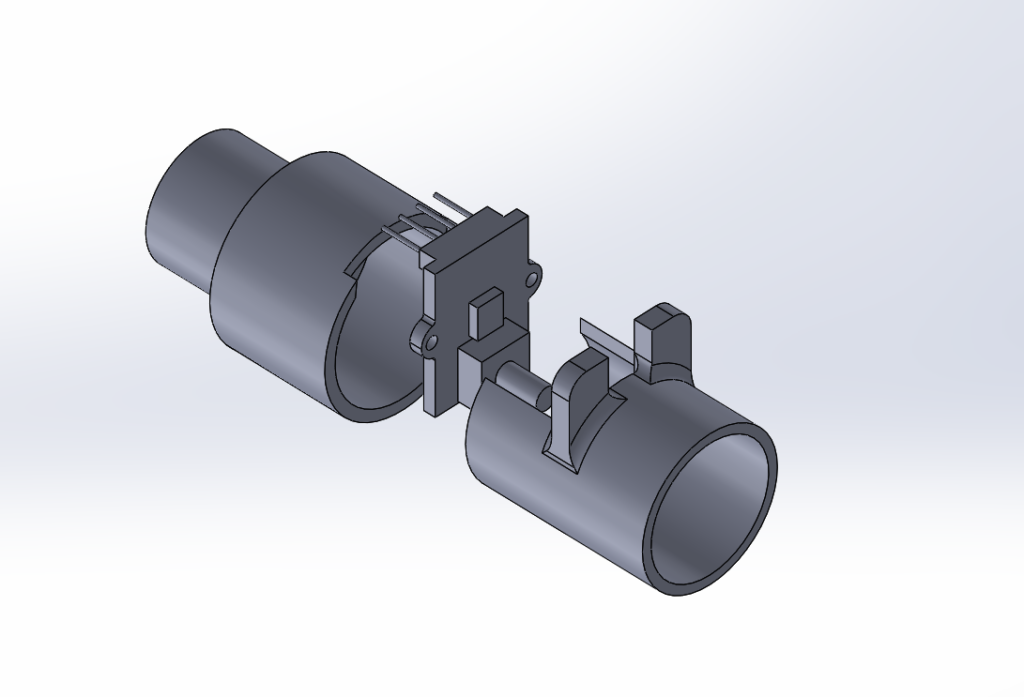
The most difficult part of this design was creating an adapter that was able to be sealed and air tight. That way, there would be an accurate pressure reading.