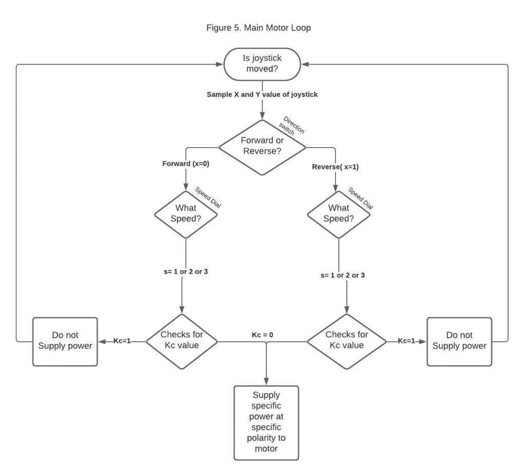
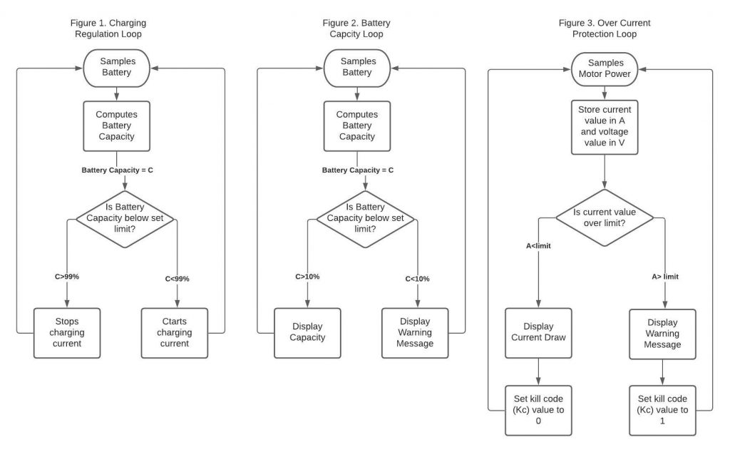
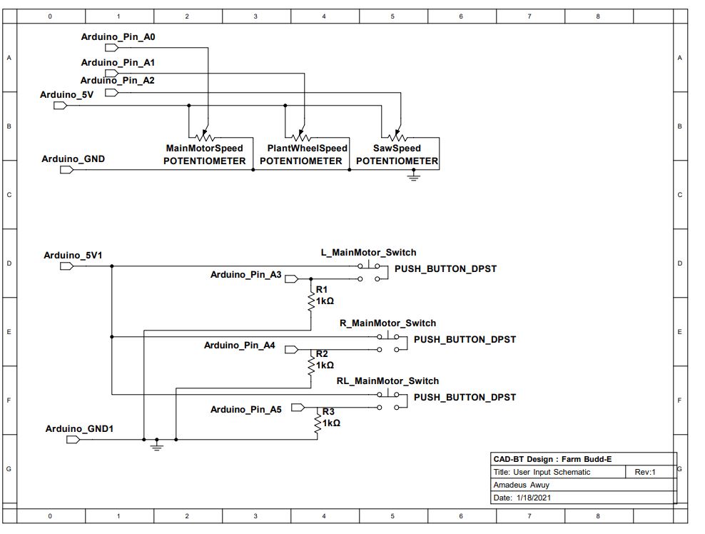
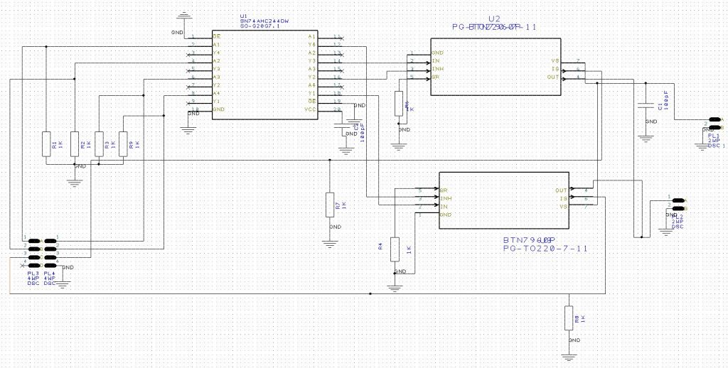
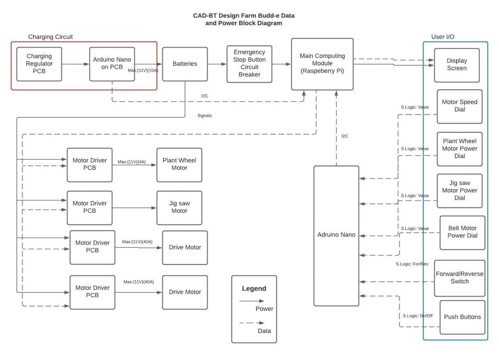
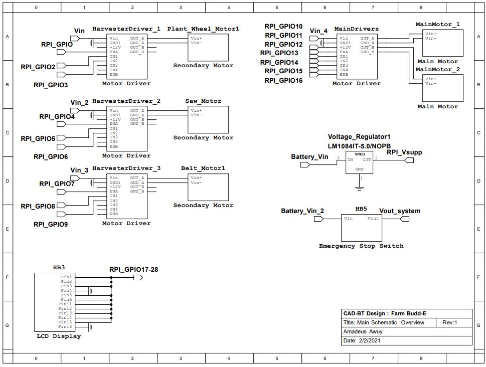
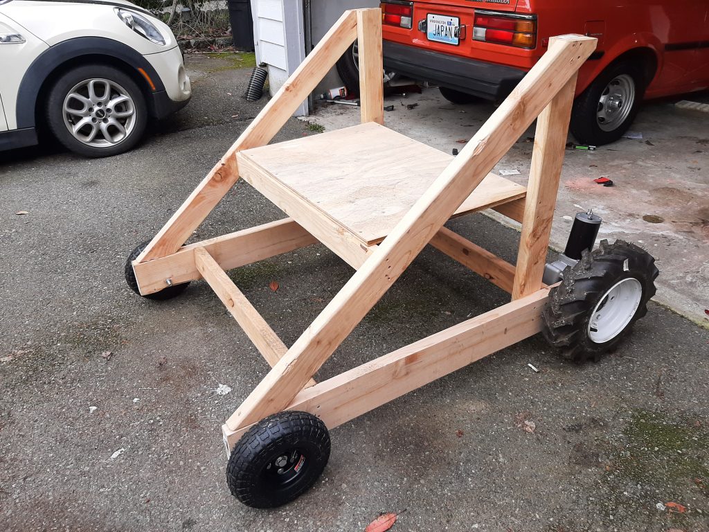
The series of block diagrams depict the routine and the loop of the coding that is used in this Project. The main function of this program is to ensure that the drivers do not exceed the set amount of current that is being supplied in the motor in order to not damage the motors. These codes also ensure that there is a level of digital safety to the software where in the event of an emergency or malfunction, the program would cease all operations of the machine. This is a collection of the initial revisions of the wiring diagrams. These diagrams include the main schematics of the motor drivers, the MCU modules that take in and process the user inputs into different outputs for the motors as well as the wiring diagram of the user input interfaces.This video demonstrates the initial joystick motor control function on the test Jig. This test utilizes the motor driver that takes in the mapped coordinates of the X and Y axes of the joystick and translates it into directional and power signals to the driver which will regulate the power to the motors accordingly.This video demonstrates the latest test of the test jig with new front swivel casters wheels. These new front wheels enable a more fluent turning operation of the test jig as well as reducing the amount of current needed by the motors to turn as the new wheels greatly decreases the frictional forces of the front wheels This is the initial RRP that was built in order to determine if the electric motors are the right type of motors to be used in this project. This RRP testing was done on a test platform that serves the purpose of simulating a specific amount of weight for the motor to “carry” around and we measured and logged the current draw of the motor. From here, we were able to extrapolate the data in order to spec our final motors for the real machine.