Mechanical Design

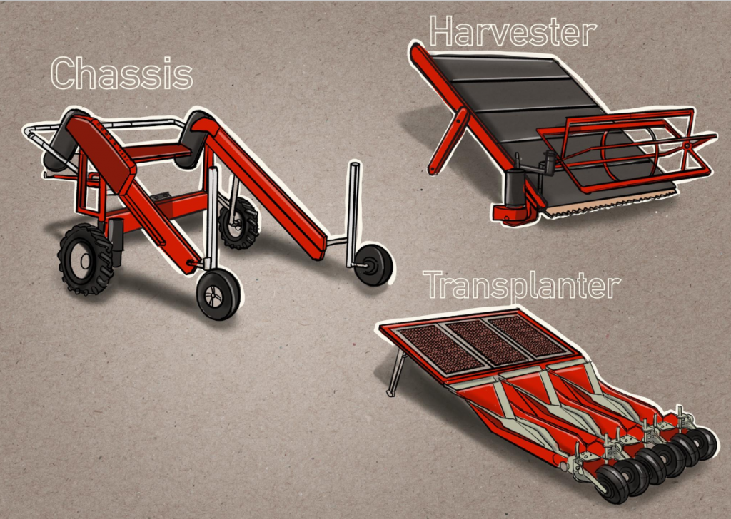
Concept Sketch:

Chassis:
11/16/2020
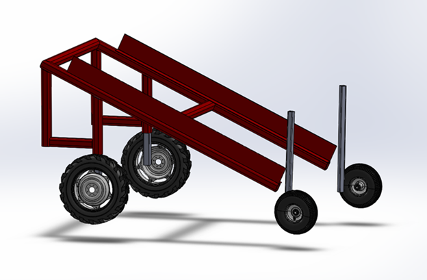
Main part of the design is finished and just needs to be put into CAD.
Still is less of a priority compared to the manufacturing RRP specs, but we are now putting more time into the CAD.
Fall 2020
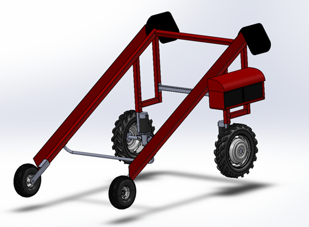
Weight analysis shows us at 165lbs so far.
Model is structurally not complete and still performs well in FEA
Control panel and operating arm not shown and will be placed on the opposite side of chassis.
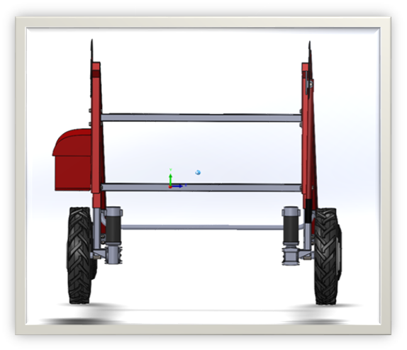
With a 5 times greater static loading the legs only have 0.021” of displacement. 


Winter 2021
We developed a new handle idea that will work well.
Front and rear adjustments for wheels redesigned.
Split the batteries and will most likely have to move them forward for balance. The mount for the batteries then would add rigidity to the legs.
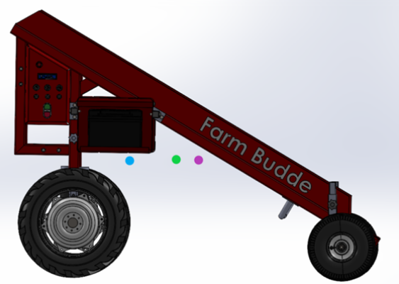
The past design of the chassis had the batteries located too far back, and without an attachment mounted to bring the COM forward we potentially could have had some stability issues. The new design of the chassis moved around parts to move the COM to a much more stable and safer location.
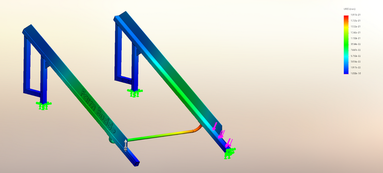
The first analysis on the chassis was to check instances of deflection or displacement. As you can see based on the scale, the major deflection can be seen in the center where there will be less support. The deflection can be seen here around less than 0.1 mm. This result tells us that there is no reason to have concern of the structural stability of the chassis with our given loads. To account for the limitations of this FEA being limited to a static load, the weight used here was 380 lbs – the same weight as demonstrated in the full wheel power video.
Spring 2021
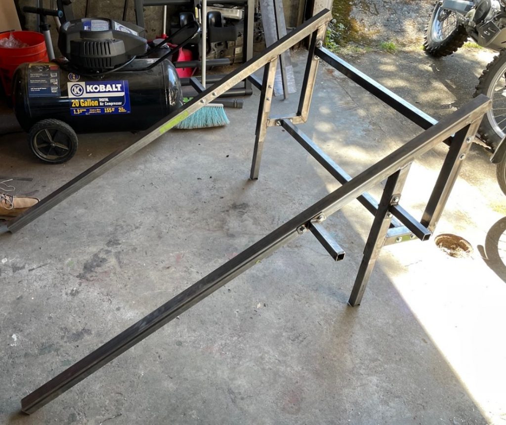
Chassis constructed from mild steel square tubing.

Mounts for Battery Trey
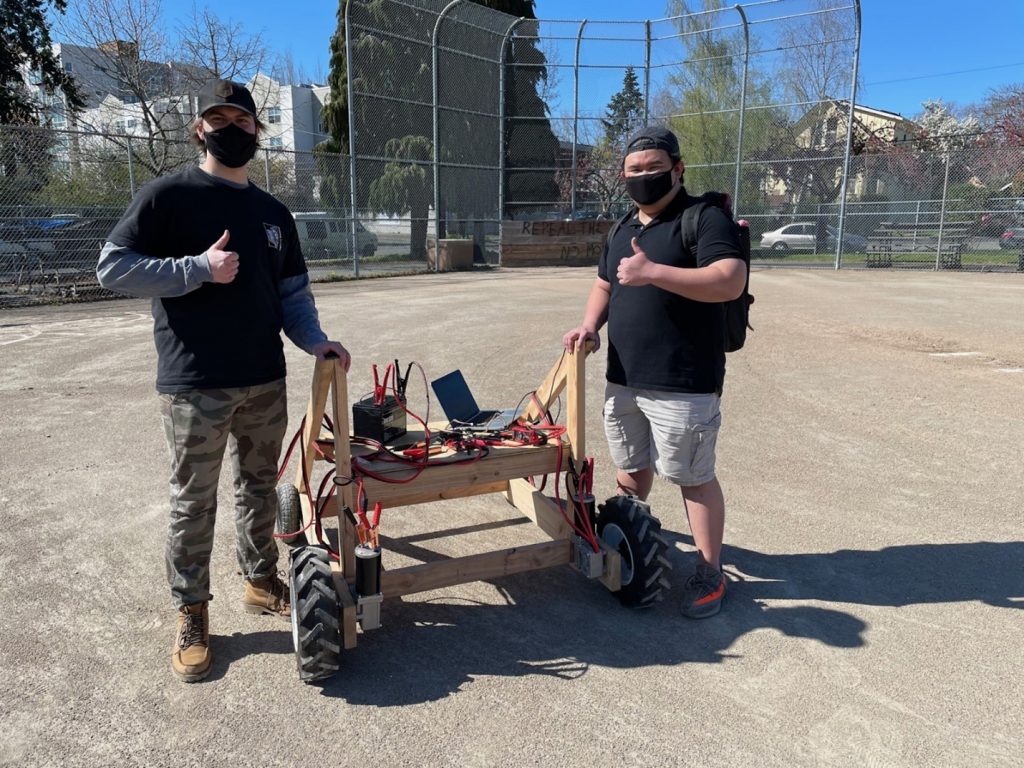
Team Members Amadeus and Taylor next to the Chassis prototype used to test motor control and function.
The wheel mounts (above), we were able to angle grind the square tube and cut to the right arc length. The tube was welded and the bearings were press fit.
Close up of one of the rear motor’s used to drive the wheels.
Transplanter was repositioned on Chassis to allow versatility. The operator will now drive the Chassis forward instead of in reverse (as before) to use the Transplanter attachment.

Harvester:

Fall 2020
CAD (via SolidWorks) of plant wheel and bandsaw assembly for the Harvester attachment
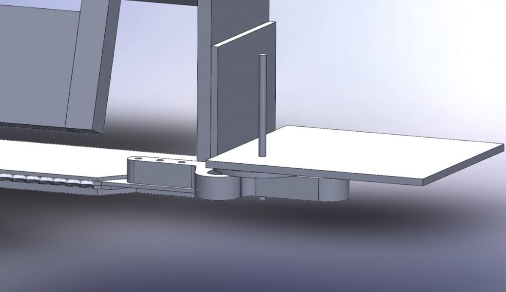
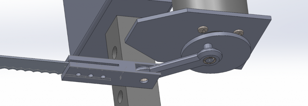
CAD of Scotch-yoke mechanism used to operate the bandsaw
3D printed Scotch-yoke mechanism.
CAD assembly of Plant Wheel including electric motor control for Plant Wheel and Bandsaw


Winter 2021
The Scotch-yoke mechanism is going to be replaced with a crank and slider after further consideration. Upon additional research of the scotch-yoke mechanism, it is evident that applications that use said systems stand vertically rather than flat. Machining of a crank and slider will be much easier
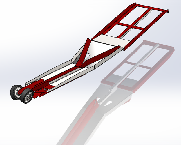
CAD for conveyor belt system aspect of Harvester (with kickstand mechanism) to allow easy installation and removal from Chassis.
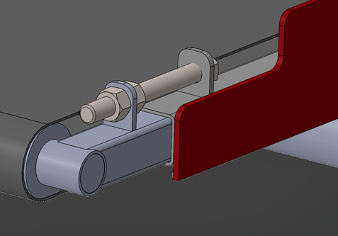
CAD assembly of conveyor belt tension system
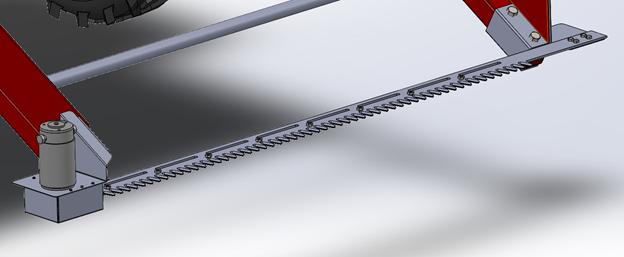
Completed CAD assembly of Bandsaw system
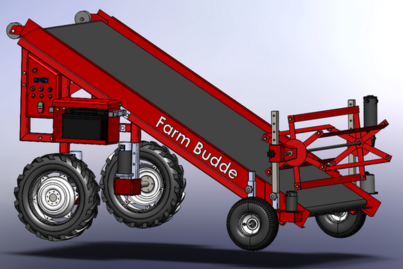
Full assembly of Harvester attachment connected to the Chassis. Band saw at bottom of conveyor belt system will cut leafy vegetables. Plant wheel will rotate and place the cut vegetable onto conveyor belt which will deliver them to bins located at back of Chassis.

Transplanter:

Fall 2020
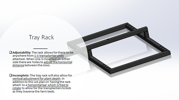
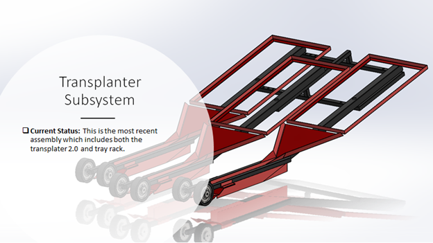
First Transplanter CAD design via SolidWorks.
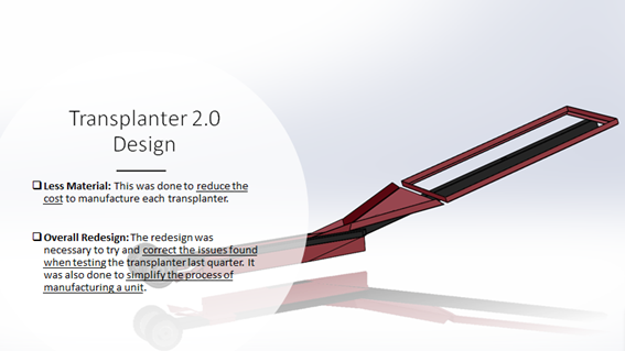
Winter 2021
Winter 2021
Spring 2021
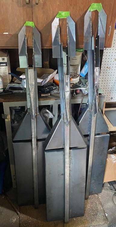
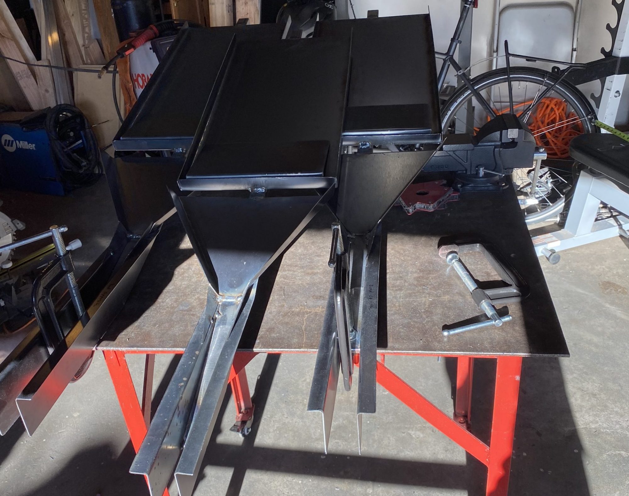
All 3 Transplanters with tray and funnel installed
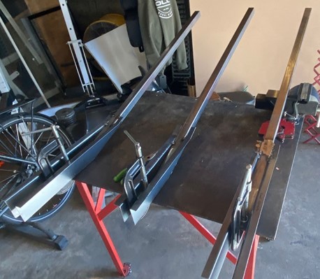
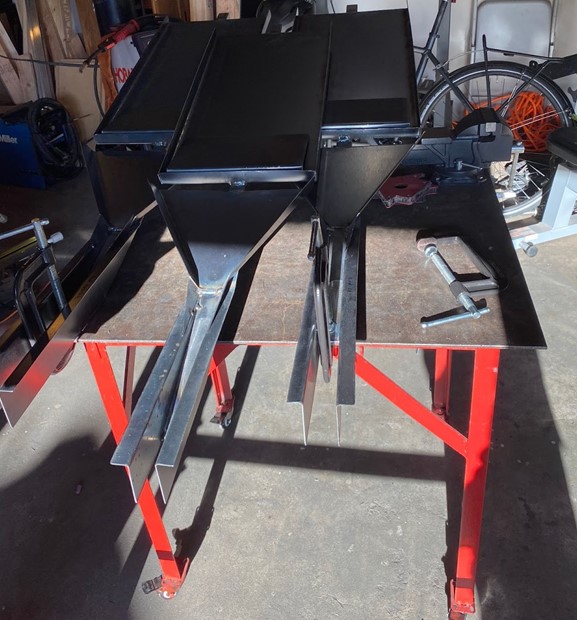
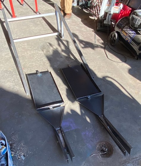
The 3 individual Transplanter frame with channel attached.
Two of the Transplanters staged in front of Chassis
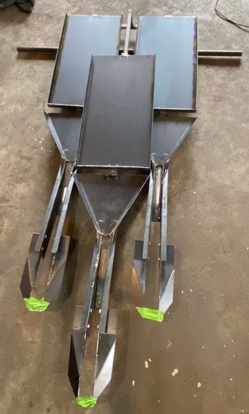
All three Transplanters with skids installed
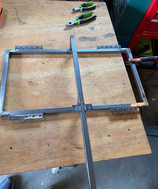
Tabs installed on Transplanter Mount to allow Outer Transplanter adjustability and center Transplanter location.