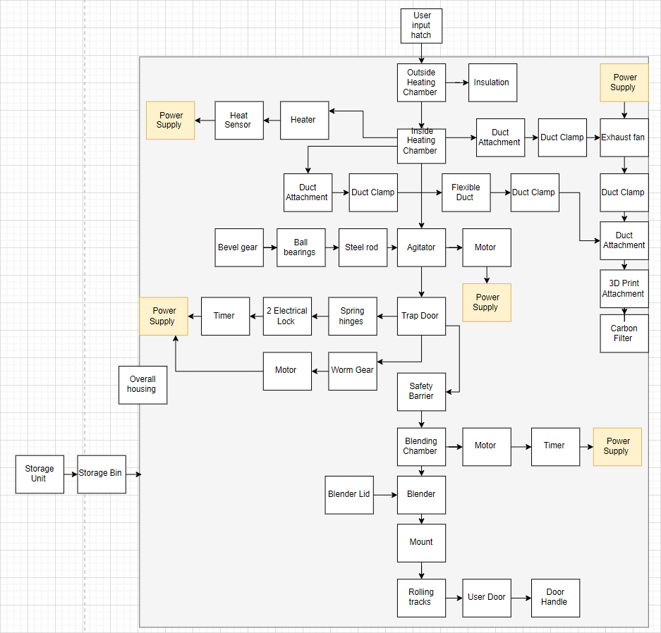
BLOCK DIAGRAM
CAD MODELS
HEATING CHAMBER
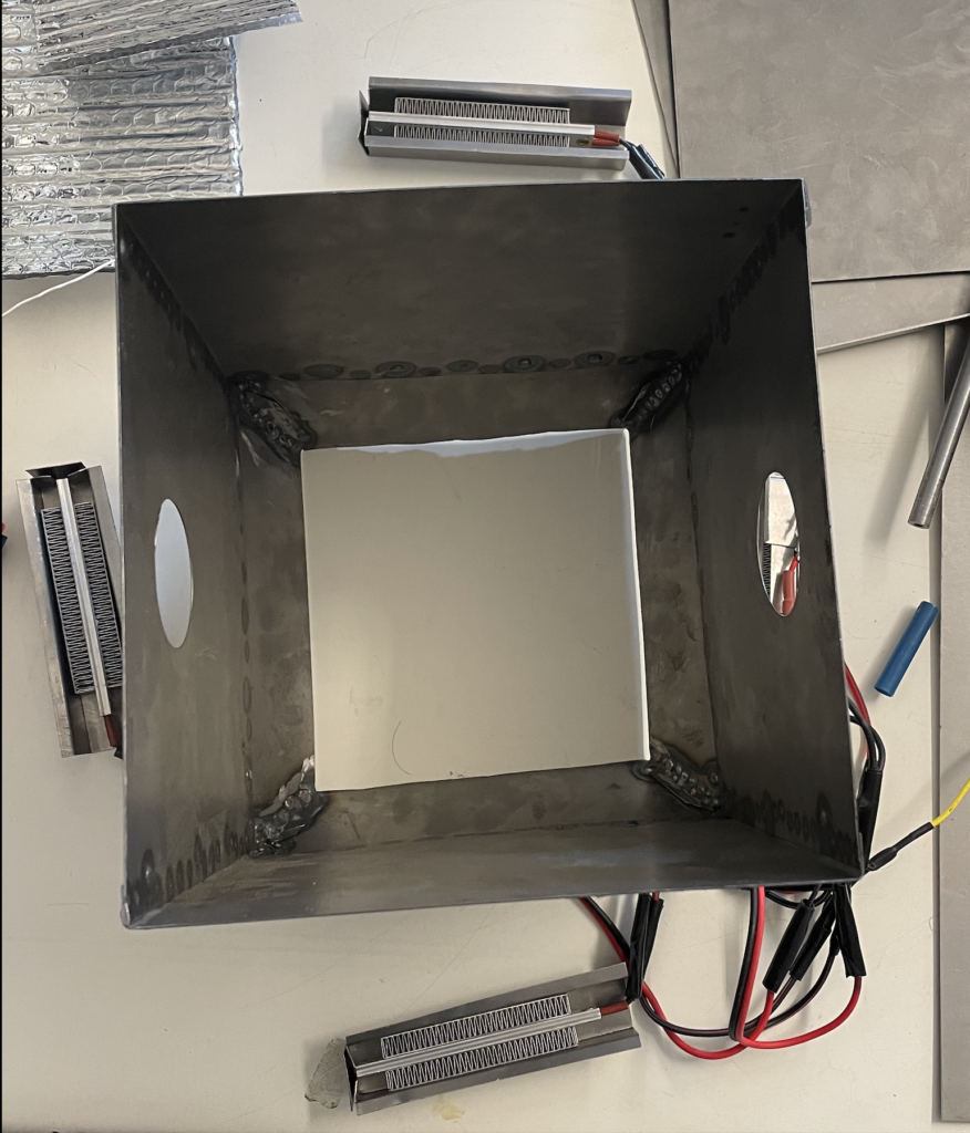
We first started our build by determining our desired size and piece of metal to weld our metal chamber first. The box is about 9×9 with the bottom of the chamber being 7×7 through the use of trapezoidal pieces welded onto the bottom of the metal box. There is also two holes on the right and left of this photo in which is our intake and exhaust outlets to allow for proper ventilation within our chamber. Furthermore, we constructed housings for our ceramic heating coils in which are welded onto the outside, located near the bottom half of our square metal chamber.
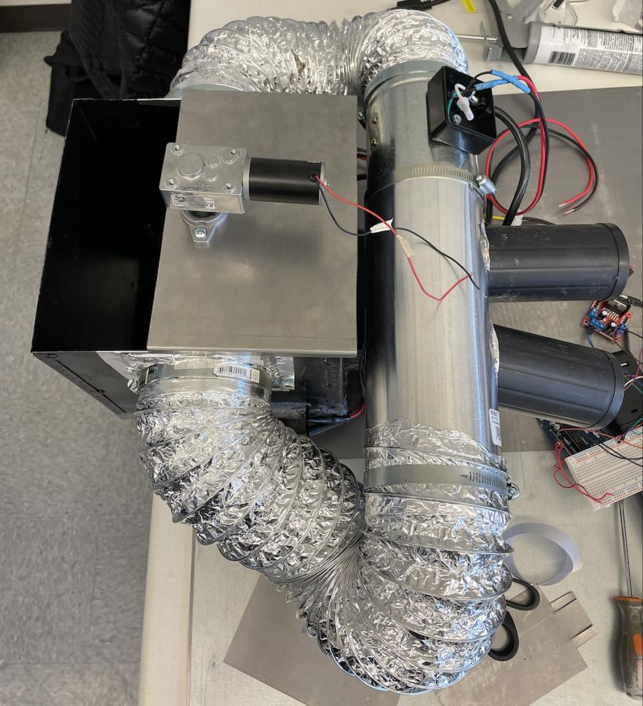
Once we constructed our metal chamber, we then integrated our ductwork which includes duct attachments, clamps, 4 in flexible ductwork, 4 in exhaust fan, and a solid 4 in duct with holes to implement our carbon filters. The flow of air is clockwise in this photo with the carbon filters located after the exhaust fan to ensure the air is being pushed out of the filters for adequate ventilation as well as reducing pungent odors from heated food waste. Furthermore, at the top of our metal chamber is our motor controlling our agitator that has a rod running down the middle of the chamber with a blade located at the bottom of the chamber.
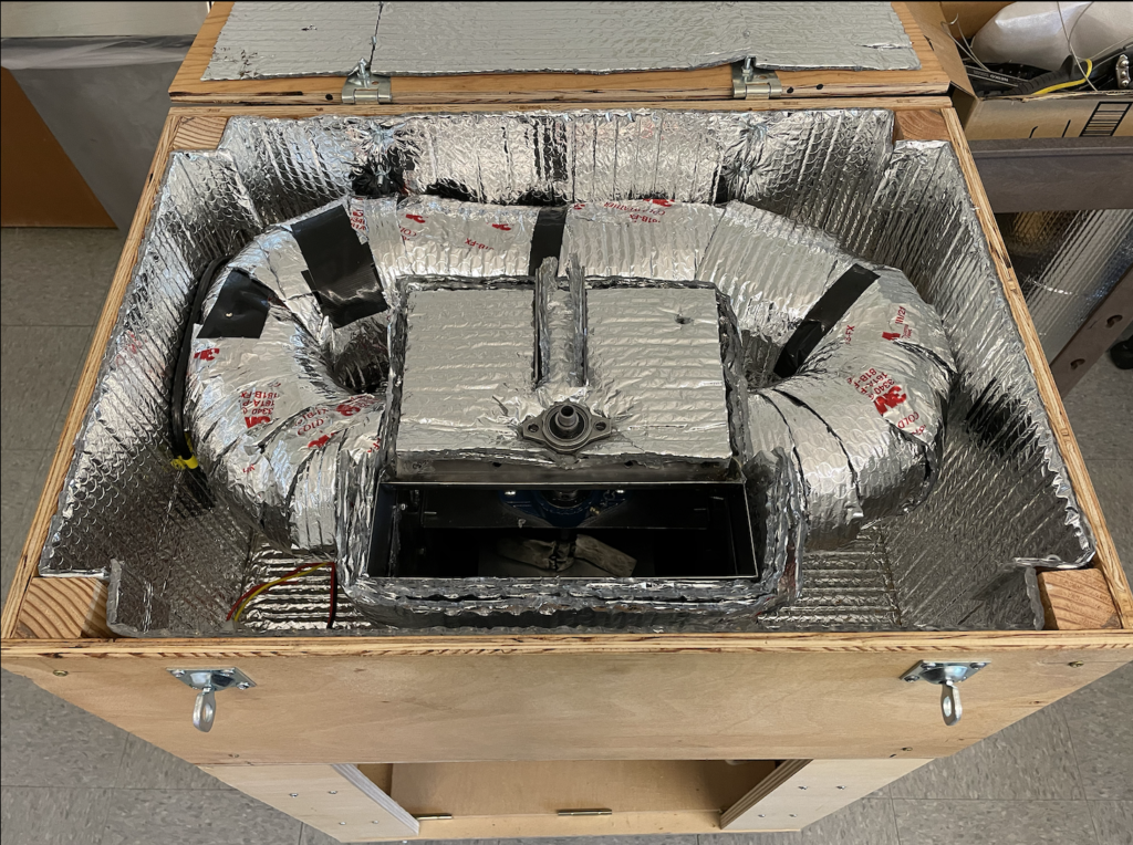
Food waste will be first inserted in the heating chamber where it will be heated, dehydrated, and sterilized to reduce the initial mass and combat odors. We are doing this by operating within a temperature range of 150-160 degrees Fahrenheit, having adequate ventilation, and carbon filters. Furthermore, with the multiple layer of insulation surrounding our whole heating system, we are able to better retain the heat within the system as well as protecting other components such as our electrical system. Lastly, we have a middle bearing support located within the metal chamber to ensure stable rotation of our agitator when moving the food waste.
AGITATOR
Within the heating chamber, the agitator is attached within the middle to help rotate the food and ensure even heat distribution of the food waste. The agitator makes sure that one piece of food waste does not overheat compared to the rest of the food waste. Furthermore, with proper ventilation, heat control, and the use of an agitator, we mitigate hazardous gas production such as methane which occurs when food is overheated
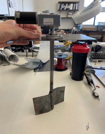
Agitator build with a motor at the top attached to our rod with set screws, a bearing to ensure proper rotation, and a metal sheet that has been shaped and heated to form blades. Furthermore, the motor is programmed to spin in both directions within a certain time frame to ensure we do not experience motor buckling.
TRAP DOOR
Once the food waste is dehydrated, it will then travel down the trap door to enter the blending phase. The trap door uses a rack and pinion system for a smooth transition to open the lid to the blender as well as add extra torque to assist the trap door in opening and closing.
BLENDING CHAMBER
Immediately after the food waste travels through the trap door, the food waste drops into the blender. In this stage, the food waste is blended until it become small pieces resembling a soil-like consistency. This will allow our food waste to be easily absorbed into the soil, speeding up the process.