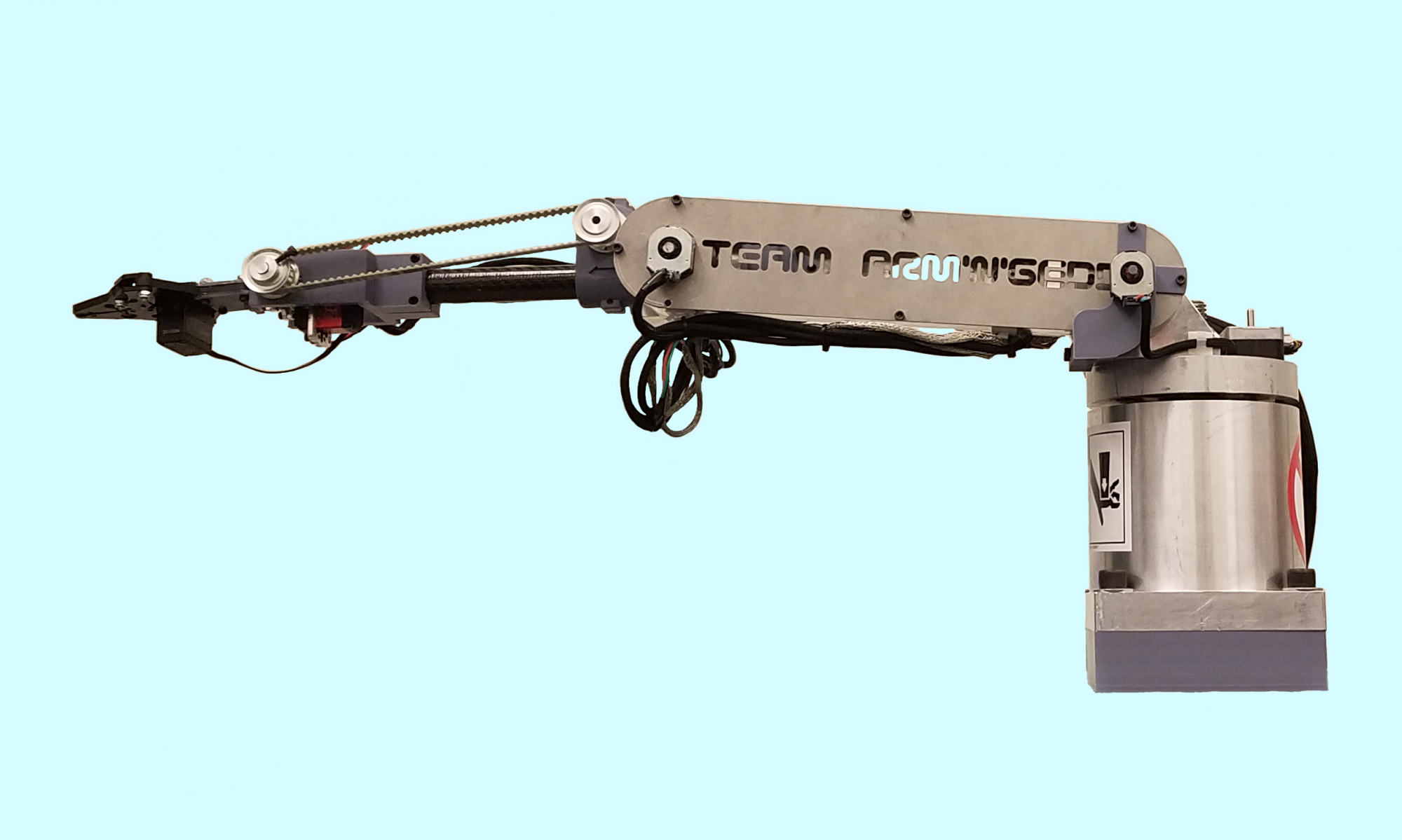
The mechanical design was one of the first focuses of our team when tackling this project. We knew that a significant amount of modeling and fabrication would be needed, and below you will find specific topics that were considered throughout the process.
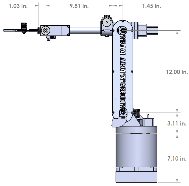
RIM’s basic dimensions can be seen below:
Why Six Degrees of Freedom?
The number of degrees of freedom (DoF) was a major consideration of ours when we were starting our project. DoF refers to the number of directions in which motion can occur; thus, having 6 DoF means we have 6 rotational joints that can move independently. A point in space can be described in many ways, but in order to capture both its position as well as its rotational position (or orientation) there must be at least 6 DoF. Eventually, we wanted the operator of RIM to be able to hold a motion controller and have the arm mimic his or her hand position and orientation. This is why we chose to build a 6 DoF system.
RIM’s layout of joints can be seen to the left. Note that there are 6 joints representing the 6 DoF. This allows the arm to reach a specified position and orientation.
Stepper Motors
Like many other robotic arms currently on the market, we decided to utilize the technology of stepper motors over other means of translating electric power into rotational motion. We chose steppers because they offered higher torque at lower speeds and we could get the precision we wanted. These benefits, combined with their relatively low cost, made this an easy choice.
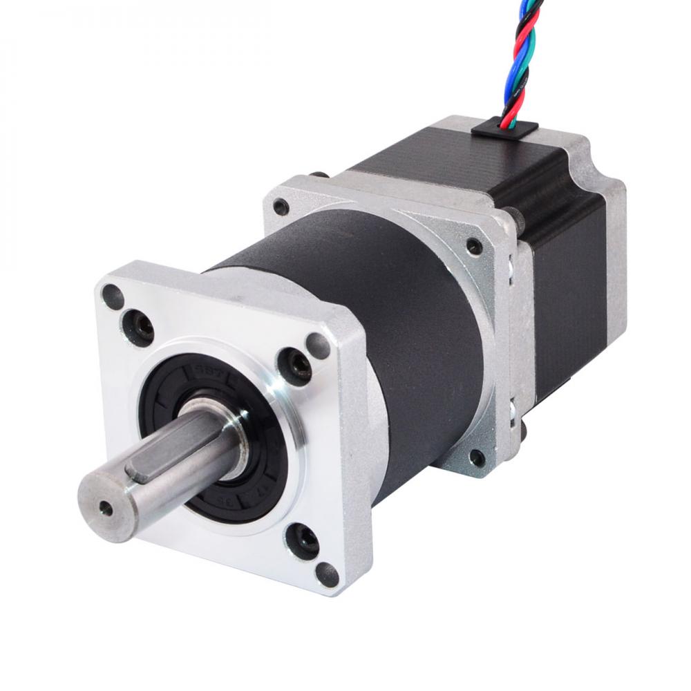
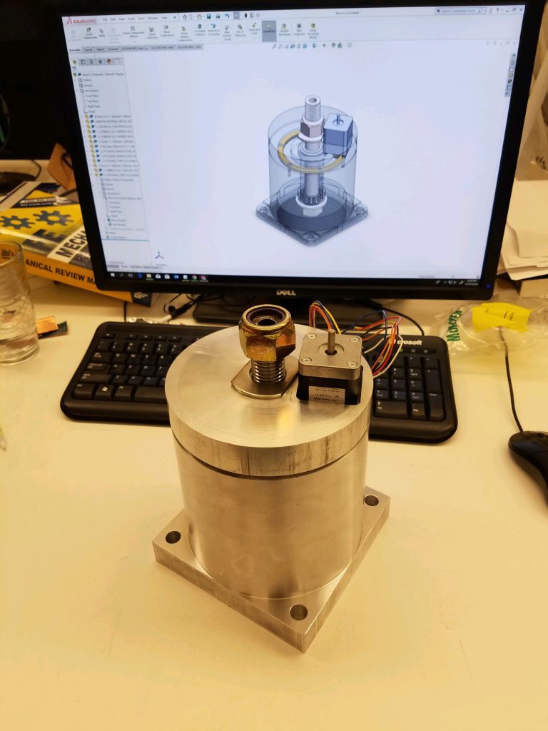
Extensive calculations were performed to determine what kind of stepper motors we were going to buy. We needed to make sure the motors could supply enough torque while holding a load and while in motion. We increased the motor’s torque output and their positional resolution by utilizing planetary gearbox systems mounted to each motor. An example of one of these motors with its gearbox can be seen to the left.
Dividing the Arm Into Sections
RIM can be broken down into 7 distinct rigid bodies. Rotational joints are located between each rigid body; thus, there are 6 joints and 6 degrees of freedom. Each rigid body can be thought of as one large part that moves relative to the other sections. This convention was used extensively throughout the design process.
The sections can be seen below:
End Effector (Red)
Wrist (Purple)
Forearm (Blue)
Elbow (Turquoise)
Arm (Green)
Shoulder (Yellow)
Base (Orange)
Building RIM in SOLIDWORKS
Once our team decided on the basic layout for the arm and the type of motors we would be using, we then started the process of building RIM in SOLIDWORKS. Our model was built initially as a tool to visualize what the arm would look like, but it quickly became one of our most critical design tools.
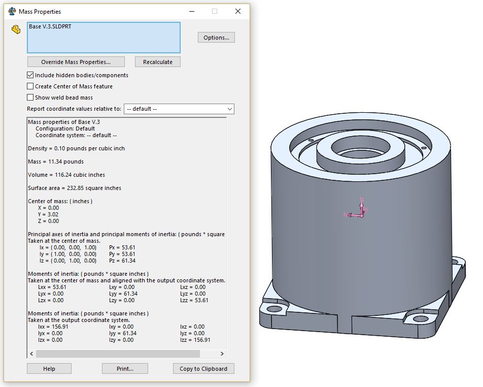
We used the model to estimate weights of each part. These weights were then used in calculations to help us choose the right motors.
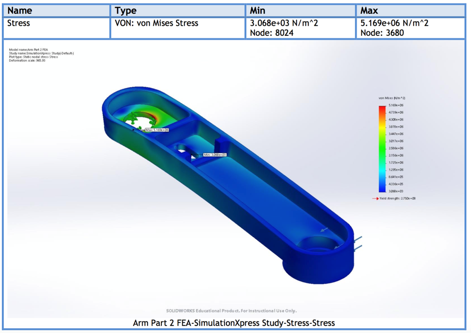
Another tool of SOLIDWORKS that we utilized is Finite Element Analysis (FEA). This helped us determine whether our parts were properly designed for the loading we expected them to experience. These analyses also influenced our decision making with regards to what materials we were going to use.
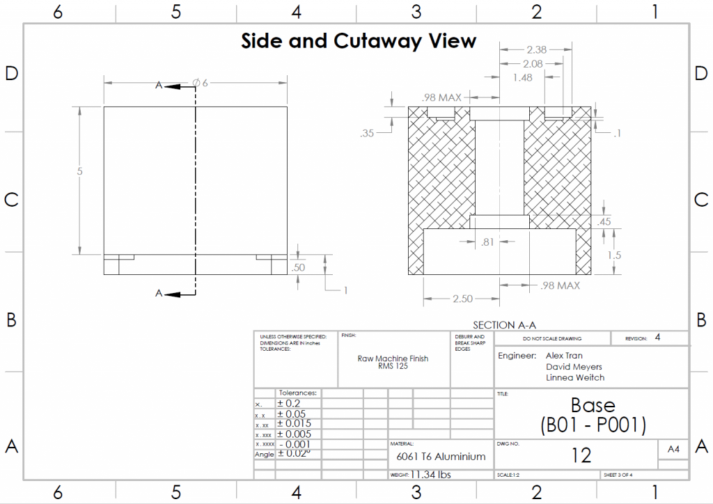
Building a 3-dimensional model in SOLIDWORKS allowed us to produce technical drawings for each part that we planned to machine.
After many months of design iterations we arrived at a final assembly of RIM. This assembly of the full arm included 7 sub-assemblies of the sections described above.
The repository of RIM’s CAD files can be found here.
The Fabrication Process
Once we had a quality CAD model and drawings of our parts, we were able to start our fabrication process. We used numerous techniques to obtain the best results for the project. The majority of the parts were machined out of aluminium; however, there is one steel shaft and one carbon fiber shaft. We also used 3D-printed PLA plastic parts to help save weight and lower cost where we could.
We started our project in the fall with a risk reduction prototype. The goal was to go through the process of designing and fabricating one of the six joints that would eventually make RIM. This allowed us to start learning about the stepper motors and it taught us valuable lessons regarding how we should design our next five joints.
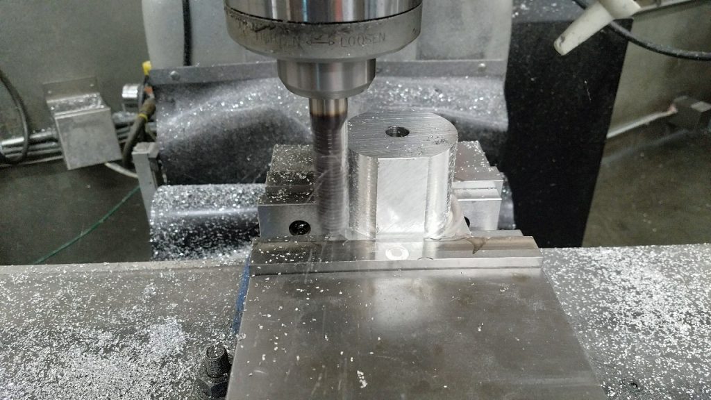
We made our aluminium parts using a traditional milling machine with driven x and y axes. The part shown to the right is a spindle that mounts to the second motor and the main arm component of RIM.
The finished spindle part is shown to the left. This is just one of many parts that needed to be machined for the project.
We would like to extend a special thank you to Carson Miller for giving many hours of his time and resources to help us successfully fabricate RIM.
Testing with a Laser CMM
One of our technical specifications for RIM was to be able to repeatedly approach a target position with the end effector. The specification stated that the end effector shall arrive within ± 1.00″ of its targeted point and should be within ± 0.10″ of its target. We ended up achieving our threshold of this specification with an average deviation of 0.2613″ ± 0.0400″.
The process we used to test this used a portable coordinate measuring machine (CMM). This machine is able to define a coordinate system calibrated to our device and then track the end effector position. We tested the arm approaching 5 independent points 20 times each. Each time we would record the final position of the end effector which we then compared to our original target position.
We attached a set of highly calibrated mirrors to RIM. These are the targets that the laser tracker locks onto and takes measurements of.