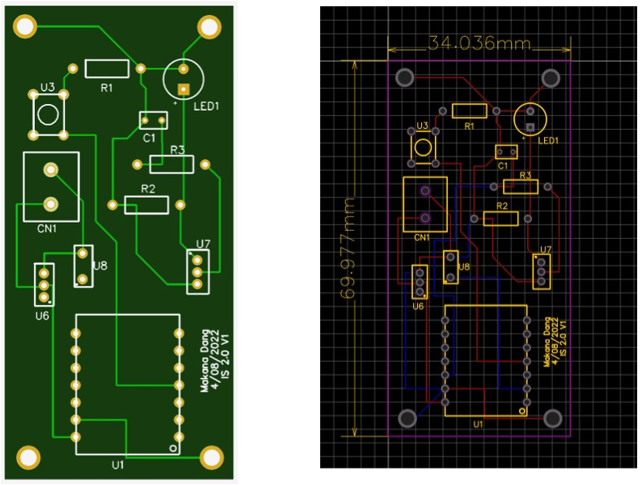
PCB Design
In terms of design for the PCB, the main component that will be soldered on is the QT Py RP2040 module. This will be positioned in the top left corner of the PCB with the switch and battery system sitting closely to the right. The batteries make sense at this position on the PCB since it is powering the QT Py RP2040 by the 5 volt pin, which is at the top right of the microcontroller. The ports for the laser emitter and receiver will sit towards the outer ends of the bottom portion of the PCB. These must be on the same general plan in order to let the laser sit perfectly perpendicular to the height of the diaphragm. We will also design the four corners of the PCB to have screw holds which also act as ground. This will allow us to ground the different components at each corner rather than on one bus line. This will also allow the PCB to be screwed into the electrical housing.
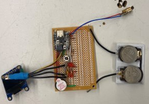
Laser Circuit and Battery Prototype
While we presented a couple of battery options in DR 2.1, they were ultimately too big for the desired size of our system and were unable to be easily interchangeable by the user within the housing. Based on the updated power consumption calculations, we needed a battery that could supply around 0.65 Watt hours at the very least. In order to accomplish this while accommodating our customers desire for size-prioritized system, we decided to utilize two CR2032 lithium watch batteries. The two 3 volt watch batteries in series with a capacity of around 235 mAh can provide a capacity of 1.41 Watt hours. This is significantly within the power consumption range we calculated prior. While the decay curve of the battery usually needs to be taken into consideration, our batteries will not be utilized for 600 hours which is where the exponential decrease in voltage begins.
Code
Since our laser sensor system only utilizes a laser emitter and a light dependent resistor, we chose to use Micro Python. Micro Python, our programming language of choice through Python interpreter (pip-installable), can be installed via operating-system package manager directly on the Raspberry Pi Pico. Our analysis produced that Thonny IDE is a great IDE to program the Pico using micropython. Because of its performance, Thonny IDE has been included by default in the Raspberry Pi’s official operating system distribution. We concluded Thonny IDE far exceeds what we require to write an optimal code for the Pico.
Through analysis of the APDS-9960 and codes that incorporate it by the sensor’s manufacturer Adafruit, we found that the necessary programming language needed is Circuit Python, an open-source derivative of Micro Python. This language interpreter and the library holding different Adafruit files essential for the sensor integration with the Pico can be installed via the Adafruit website. This package also had to be installed and changed in Thonny.