Ergonomic Spirometer
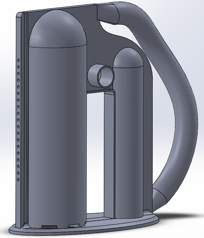
Our customer, Mr. Kerry Curran, expressed interest in having us redesign the incentive spirometer so that it could not only integrate an OPEP device and have good ergonomics, but also have improved aesthetics and ergonomics with a more modern design. We accomplished the aesthetic/ergonomic portion by introducing a more modern design, and having the handle angled so that the user/patient would not tilt the device while completing their prescribed therapy. WE also added a space and rail system fore the OPEP device to be integrated. Another Updated feature on this design is the electrical component mounting system with can be seen on the left of the picture above. This system allows for the electrical component to be moved to different levels of the spirometer in order to meet a doctors prescription.
Electrical Housing
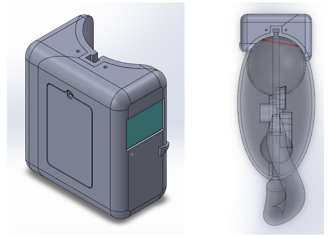
The Electrical Housing is an important aspect of this design project as it is responsible for the integration between the electrical and computer systems with the Spirometer. The housing contains the batteries, the PCB board, the laser sensor, or well as the on and off switch. The image above shows the laser passing through the Spirometer diaphragm and reaching the laser sensor which allows for the patients successful inhalation to be recorded. The electrical housing also needed to be able to move up and down the side of the Spiromter so that it could be set to different prescribed volumes by the doctor. We approached this problem by introducing a rail system on the side of the spirometer and a spring-pin system on the electrical housing, which allows for the electrical housing to move along the rail system on the Spiromter
OPEP Device
The OPEP Device or Oscillating Positive Expiratory Pressure Device is an exhalation therapy device that helps remove Phlegm from the patients lungs.
Initially we wanted to use similar techniques used in the Aerobika OPEP device to create an adjustable oscillation in our OPEP device. We dedicated a few weeks to studying the Aerobika and other OPEPs on the market to figure out what are the necessary components to create an OPEP device. From our observations we found that most OPEP devices have 2 chambers for air to travel through, 1 with air to flow with relatively low resistance, and the second to create an oscillation with outlets facing the opposite direction of air flow.
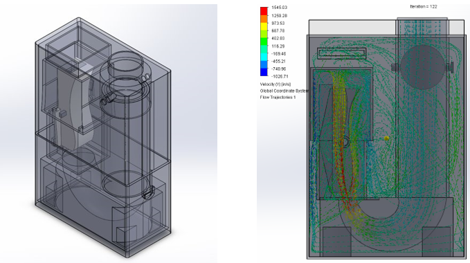
When designing our oscillating mechanism, we took inspiration from the aerodynamic technology used in the under floor of Formula 1 cars used to create downforce. Essentially these cars use the venturi effect to create an area of low pressure under the car by squeezing the air causing it to accelerate into a diffuser. Our design uses similar logic by creating an area of low pressure in the air channel, but we added some aerodynamic features to the front and rear end to offset the balance and create an oscillation about the axis of the air channel. The location of the axis is another key element for creating an oscillation as the air channel is allowed to rotate about this axis. Depending on the location of the axis we can give we can facilitate the ability of either the front or rear end to cause a rotation by increasing the moment arm.