Fall Quarter Design
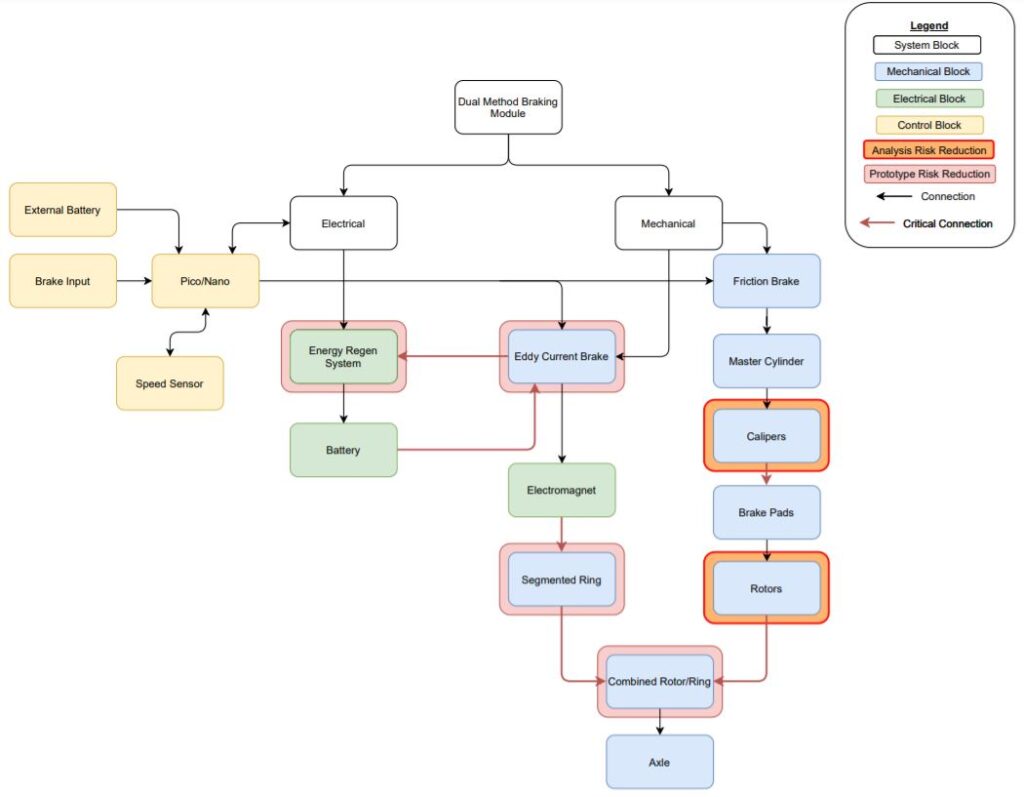
At the beginning of our project, we were tasked with figuring out how we wanted to apply the eddy current phenomena to existing automotive braking. We brainstormed the key ideas that we wanted to incorporate into our project, which included a friction braking system, a hydraulic braking system, and a regenerative braking system (which was ultimately scrapped for simplicity). Below is our block diagram:
Out initial plan was to build a test stand that was designed to stop a modified bike tire using small electromagnets purchased off Amazon. We planned to attach a magnetic ring to a bike tire, spin it at a set speed, alter the amount of current sent to the electromagnets placed a set distance away, and then record how much change in rotational velocity we are producing for each level of current. We can control our delivery of current using a current generator in one of the labs on-campus.
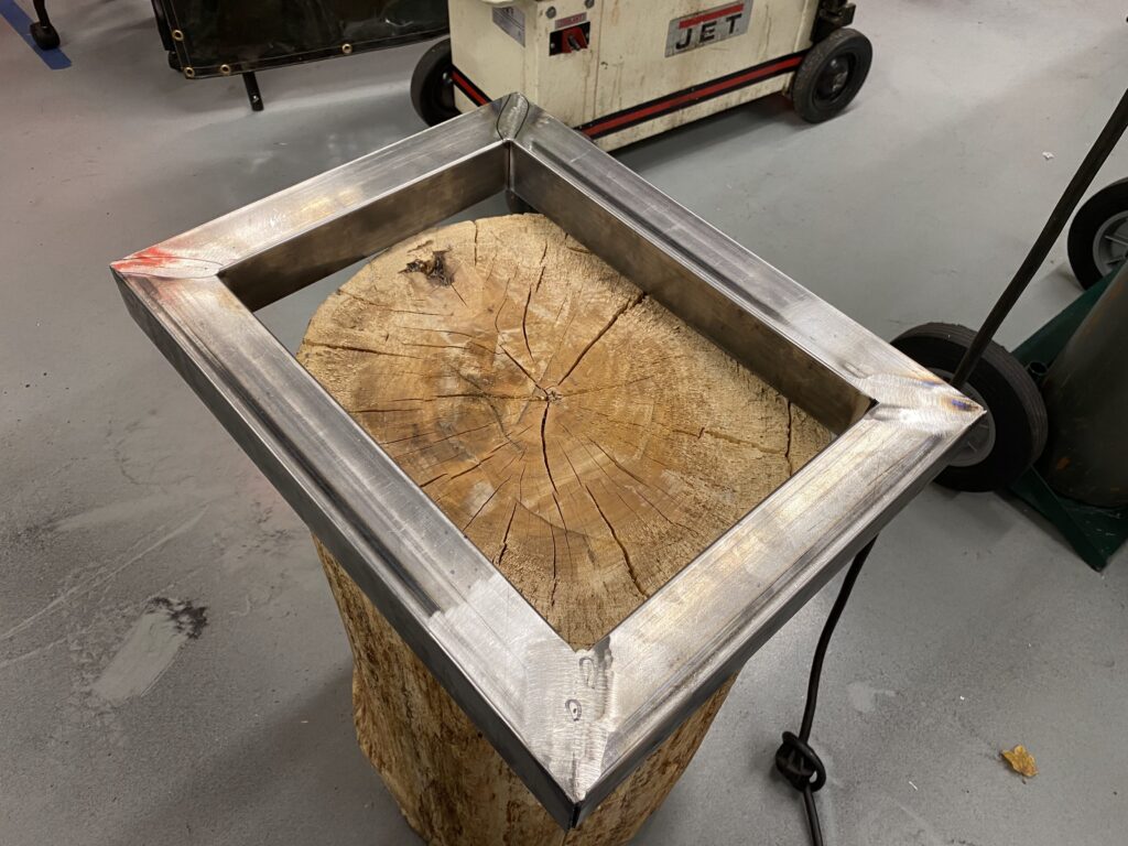
We began the fabrication of the stand using 2-inch square steel tubes welded together, as pictured below. By using hollow tubes we were able to reduce costs, and fill it with sand to improve vibration dampening.
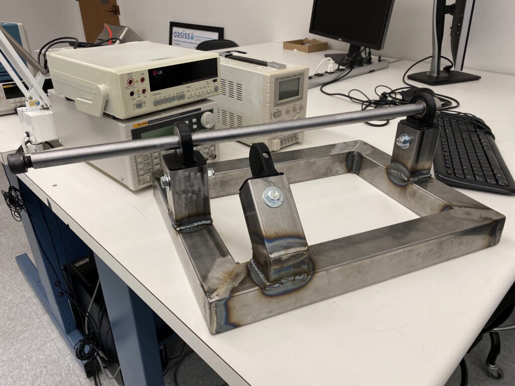
Pictured below was the next step in the manufacturing process that consisted of welding three more 2-inch square tubes to the stand’s base. Two of which were supporting the 3/4 inch axle, while we 3D-printed custom mounts that we seated ball bearing in. The third of the square tubes was for our electromagnet mount with a similar 3D-printed mount.
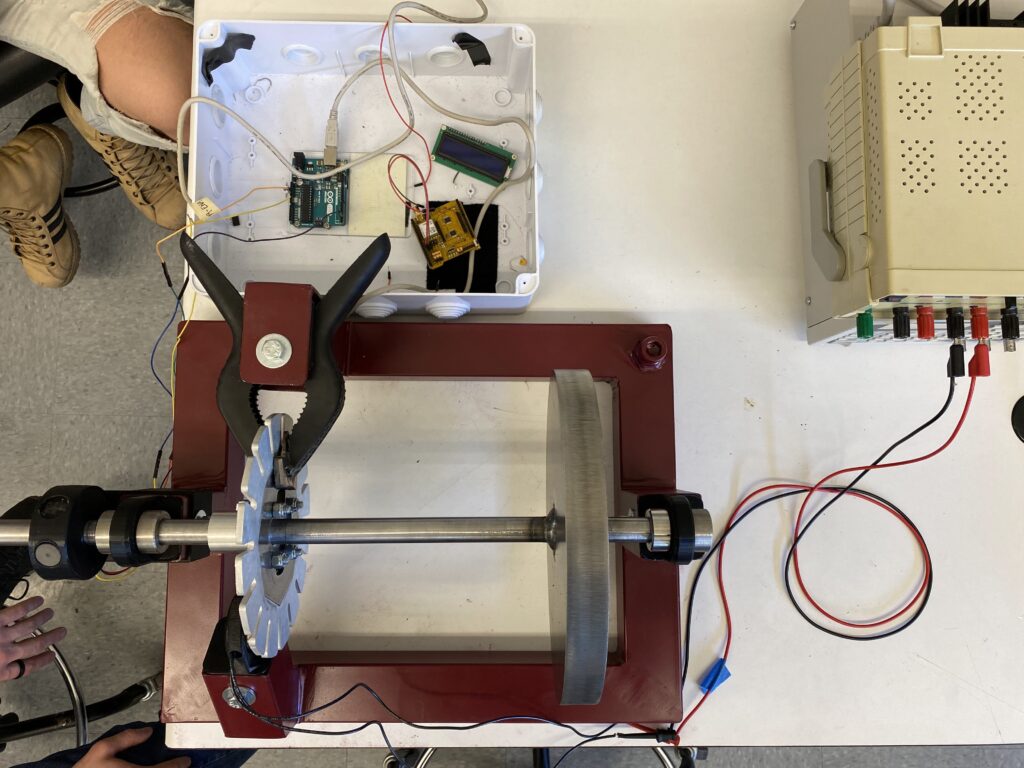
By the end of Fall Quarter, we had a painted stand (pictured below) with a single electromagnet mounted along with a makeshift friction brake, using the current generator we were able to successfully induce eddy currents in the aluminum part of our brake disk and slow it down faster, even if marginally. The large disk on the right side of our axle was intended to add more angular momentum to our axle as it would have in application. This test stand combined with our microcontroller measuring the speed we were able to get an accurate reading on whether the electromagnetic braking would be viable.
Winter Quarter Design
With our initial testing giving us promising results we redesigned and updated our Block Diagrams for our mechanical, electrical, and software subsystems. Which gave us an idea of what parts we needed to purchase to make our project happen.
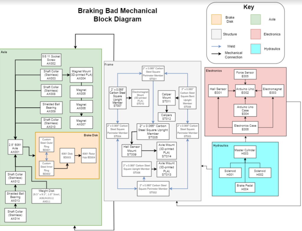
The Mechanical Diagram shows all the parts that we needed to build our prototype including the casing and the nuts and bolts to keep it all together.
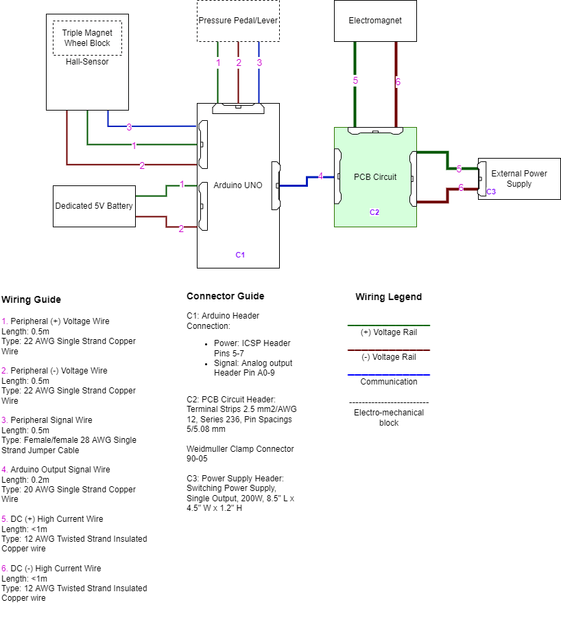
The Electrical Block, shows the connections of the different electrical parts, including the connection between the Electromagnet and the PCB circuit and it’s External Power supply
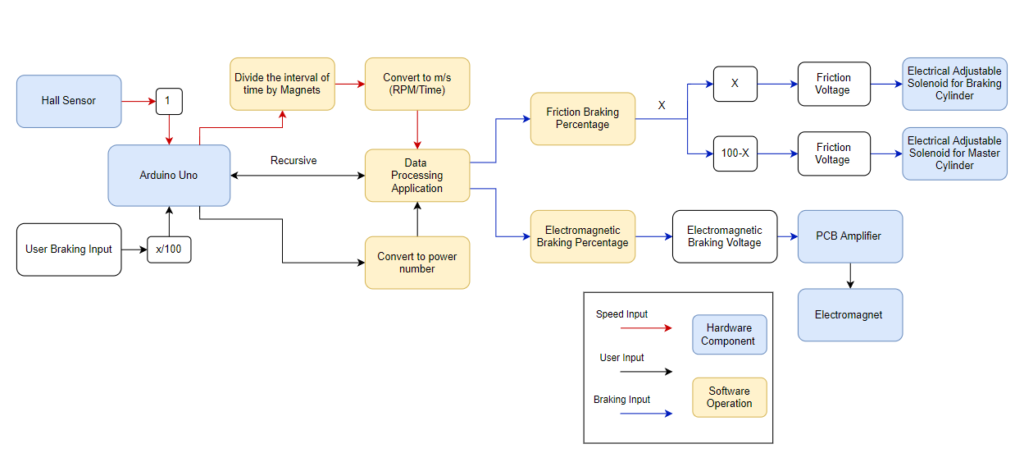
The Software and Firmware Block diagram shows how the Arduino Uno takes the Hall Sensor and a user input and converts it to a friction voltage and electromagnetic voltage. This requires an intricate data processing application that converts the force on the force-sensitive resistor into a comparable number and finally ends with a hybrid system
While the beginning of the quarter started off strong due to delays in shipping (partially because of a global pandemic) we were unable to continue at the pace we had at the start. Even with the turbulence, we ended the quarter with an almost fully functional system that just needed some tweaking in order for us to start testing.
Spring Quarter Design
After getting our system up and running the last thing that was on our docket was to test and tinker to get our desired results