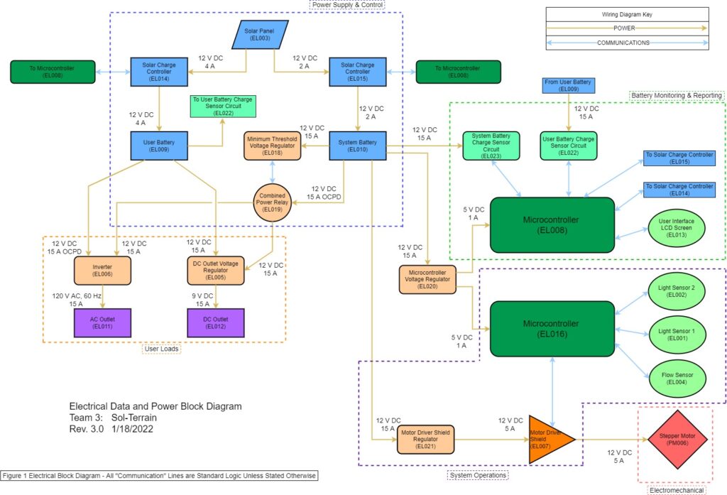
Team Sol-Terrain has designed a sustainable energy source to supplement the energy consumed by residents within Pallet’s Shelter villages. The figure above is an electrical block diagram with electrical component numbers to use in the following description. A solar panel (EL003) will be used to achieve the sustainable energy source, which will store energy within two batteries, a 12Volt, 20 Amphour system battery (EL010) and a 12Volt, 35 Amphour user battery (EL009). The user battery will be used to power the loads placed on the system by the resident through either the DC outlet (EL012) or the AC outlet (EL011). The power output at the AC and DC outlet are 12 VAC, 60Hz and 9V DC respectively due to the inverter (EL006) and DC Outlet Voltage Regulator, a Buck Converter (EL005). To regulate the charge on the batteries to limit electrical degradation, the solar panel first connects to solar charge controllers (EL014 & EL015). These monitor the state of the battery and disconnect the power supply of the solar panel if the battery is fully charged. The system battery is used to power the system’s microcontrollers (EL008 & EL016) and the solar panel’s stepper motor (EL007). The microcontrollers’ power supply from the system battery is regulated by a buck converter (EL020) to ensure the microcontrollers do not get damaged from too large of a power source. The purpose of the microcontroller (EL016), an Arduino Uno model, is to communicate with multiple sensors in order to determine the operating mode and the position of the sun. Two light sensors (EL001 & EL002) will be fixed onto opposite sides of the solar panel and will communicate UV light values to the microcontroller to indicate where the sun is moving. When the two light sensors’ values differ enough, the microcontroller will run the motor driver shield (EL007) to drive the stepper motor (PM006), turning the solar panel towards the direction of the light sensor reading a larger UV light value. However, if there are not enough UV light values received into either light sensor, or the flow sensor (EL004) in the affixed gutter reads water flowing through, then the microcontroller will run the motor driver shield to drive the stepper motor to turn the solar panel to its set rest location. In this rest location, the solar panel will direct rain flow into a gutter for collection. The microcontroller (EL008) will read the values of the system and user battery charge sensor circuits (EL022 – user & EL023 – system) and display their values on the user interface LCD screen (EL013). Finally, the system battery will also supplement the power supplied to the AC and DC outlets. However, to ensure active mode operation of the system, a minimum threshold voltage regulator (EL018) will monitor the system battery’s charge. Once the battery discharges to the threshold value, the minimum threshold voltage regulator will communicate with the combined power relay (EL019) in order to cut the power delivered from the system battery to the outlets.
Wiring Diagram
The figure above depicts the physical wiring connections between the different electrical subsystems.